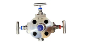
Monoflange or flanged manifold: the most compact way to isolate and vent instrumentation
Do you really know what a monoflange is and when it’s worth using one? I usually explain it like this: if you have several valves,
How we love to see the word “free” in the titles.
But things as they are. Read on to download the symbols of a needle valve.
Needle valves get their name from the needle-shaped internal stem or shaft. When designing a piping system, isometric, or installation, the valve is represented by the symbol schematic needle valve.
If you want to download the needle valve symbol, you are right. Enter your favorite email and click on it. You can download it in several formats hehe
Piping and instrumentation system schematics are simplified representations of systems that can be complex and in which the components are represented by their schematic symbols. This is why it is essential to use the proper schematic needle valve symbol to avoid errors during installation or replacement.
On the other hand, drawing a needle valve is more complex and detailed. It can be made in two or three dimensions, and its parts can be identified. This type of representation is used mainly by the valve manufacturer to detail the components, materials, and design tolerances of the needle valve. In these cases, the drawing is used with a cross-section of the valve to show the inside of the valve.
The schematic symbol is obtained using a bow tie symbol with an arrow pointing down in the center. It has a 2-way valve symbol with an indicator showing that it is a needle valve. In addition, it is possible to indicate whether the needle valve is in the closed or open position by placing the arrow touching the center of the bow tie or not respectively. It is beneficial in instrumentation schemes.
In addition, it is also possible to indicate the type of valve connection. The following is added for this purpose:

Avoid problems by downloading the symbols of a needle valve. Click on it 😉
When working with drawings, diagrams, and DRAWINGsymbols digitally, it is necessary to know the file types to work with.
The STEP file refers to the “Standard for the Exchange of Product model data file.” It is a standardized CAD file used to share designs between CAD software. STP is simply another extension used for this file type, so there is no difference between a .step file and an .stp file; both comply with ISO 10303.
The STEP format (*.step, *.stp) contains all the information about the 3D valve design and saves it as a series of text documents. These are the file types used in valve design drawings mainly.
Drawing or dwg is another file type used for needle valves at the digital level. DWG files are closely associated with CAD (Computer-Aided Design) programs. They are files containing two-dimensional and three-dimensional vector graphics. Specialized CAD software is required to open these files.
As I said before, CAD stands for Computer-Aided Design. There is a wide variety of CAD software on the market. Autodesk’s AutoCAD is one of the most famous. Many times we call a pre-designed drawing Block or Block.
AutoCAD 2D contains a library of symbols, including the needle valve schematic symbol with built-in attributes for size. Download the needle valve symbol schematic to choose between .dxf or .dwg, depending on your CAD version.
Last chance goes. I know you want it. Download the symbols in .pdf .jpg .dxf .dwg. Click on it 😉
If you want to learn more about our needle valves or have any questions, please do not hesitate to contact our experts. This allows the flow to be controlled and regulated with good precision.
Do you really know what a monoflange is and when it’s worth using one? I usually explain it like this: if you have several valves,
Imagine you’re running an industrial plant and you’ve got a diaphragm seal protecting a pressure transmitter. Over time, the process fluid starts leaving deposits and

One Response
wow nice information