
Redfluid obtains BV Mode II recognition from Bureau Veritas
It’s official! Redfluid has been recognized by Bureau Veritas under the BV Mode II scheme — or as we call it in the industry, Company
With this there is always a huge hassle.
But well, that’s what we are here for. Let me explain a little bit the difference between these products that are in the MSS-SP standards. And the best: I leave you specific info for each one (and a very useful data sheet).
Let’s get down to business.
The MSS SP (Manufacturers Standardization Society of the Valve and Fittings Industry) standards are a set of standards developed by the Manufacturers Standardization Society in the valve and fitting industry. These standards are used to establish technical criteria and specifications for products related to valves, fittings and equipment in the process industry.
MSS SP addresses a variety of products, from valves to flanges, fittings, accessories and other components used in industrial piping systems. These standards seek to provide guidelines and specifications to ensure the quality and interoperability of products used in the industry.
These standards are used by manufacturers, engineers and industry professionals to ensure the consistency and quality of products used in piping systems, which contributes to the safety and efficiency of industrial processes.
Well, it has many forms. But let’s go to the definition:
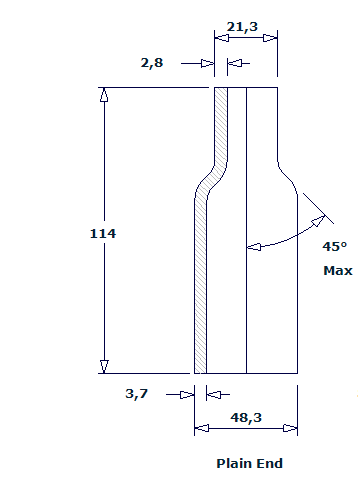
A “Swage Nipple” is a fitting used on pipes and piping systems to connect two pipes of different sizes. It is also known as a “nipple reducer” in some cases. This fitting has two threaded or notched ends, each designed to fit a specific size of pipe. It may also be identified as a Reduced Nipple.
Here is an example of a Swage Nipple. In this case it would be flat on both sides.
That is to say, it can be threaded on one side, on two sides, on neither side…
What exactly are the dimensions of the MSS SP 95 2000 standard?
Well, very easy and precise:
Here are some measurements (the most demanded) that will be useful when ordering a Reduced Nipple (I leave them in inches).
| Nominal Pipe Size | OD long end | OD short end | Length |
| 1/4 x 1/8 | 0,540 | 0,405 | 2,25 |
| 3/8 x 1/4 | 0,675 | 0,540 | 2,50 |
| 1/2 x 1/4 | 0,840 | 0,540 | 2,75 |
| 3/4 x 1/2 | 1,050 | 0,840 | 3,00 |
| 1 x 1/2 | 1,315 | 0,840 | 3,50 |
| 1 x 3/4 | 1,315 | 1,050 | 3,50 |
| 1-1/4 x 1/2 | 1,660 | 0,840 | 4,00 |
| 1-1/2 x 1/2 | 1,900 | 0,840 | 4,50 |
| 1-1/2 x 1 | 1,900 | 1,315 | 4,50 |
| 2 x 1-1/2 | 2,375 | 1,900 | 6,50 |
| 2-1/2 x 1-1/2 | 2,875 | 1,900 | 7,00 |
| 3 x 1-1/2 | 3,500 | 1,900 | 8,00 |
| 4 x 3 | 4,500 | 3,500 | 9,00 |
| 5 x 3-1/2 | 5,563 | 4,500 | 11,00 |
And if there is a size you don’t see in the table and you need a Swage Nipple with maximum need, click HERE. I’ll give you a hand.
When ordering a Swage Nipple you have to be very careful with abbreviations. More than once, I’ve been asked for something I didn’t mean. And then it’s time for what it takes: the return. Here, I’ll show you:
Example:
If you have a Swage Nipple that is threaded on the long side and flat on the short side, you must order a Swage Nipple T.L.E. (Threaded Long End) and P.S.E. (Plain Short End).
Pretty simple, isn’t it?
In the end it all comes from the Nipple family. And so that you don’t make a mistake ordering your Reduced Nipple, or any type of Nipple for that matter, I recommend you read the article on how to order your Nipple by clicking HERE.
And also (of course), I’ll pass here the technical data sheet. It is important that you have it at hand every time you order a Nipple:
MSS SP 83-2006 establishes the standard requirements for union nuts used in threaded pipe fittings. In particular, it refers to union nuts for threaded end connections on steel pipe ends.
A “union nut” is a threaded part used to join two threaded pipe ends. These nuts are critical components in piping systems and are used to provide a secure, watertight connection.

Pretty easy to understand, right?
Now, let’s dig a little deeper into this standard.
Each standard offers us different levels.
What does this standard that talks about Union Nuts provide us with? Let’s go:
In this case we differentiate whether the union nut is threaded or welded (SW).
In this case, the standard offers several specifications that will help us when ordering the union nut. The MSS SP 83 2006 standard gives us information on the following:
I give you all the measurements in inches, which is how the standard measures: (in inches)
| Nom. Pipe Size | Pipe End Minimum | Wall Minimum | Water Way Bore | Male Flange Minimum | Nut Minimum | Nominal Lenght |
| 1/8 | 0,58 | 0,095 | 0,332 0,253 | 0,125 | 0,125 | 1,63 |
| 1/4 | 0,75 | 0,119 | 0, 438 0,372 | 0,125 | 0,125 | 1,63 |
| 3/8 | 0,90 | 0,126 | 0,562 0,532 | 0,135 | 0,135 | 1,81 |
| 1/2 | 1,09 | 0,147 | 0,703 0,672 | 0,145 | 0,145 | 1,93 |
| 3/4 | 1,32 | 0,154 | 0,906 0,842 | 0,160 | 0,160 | 2,24 |
| 1 | 1,63 | 0,179 | 1,141 1,092 | 0,180 | 0,175 | 2,44 |
| 1-1/4 | 1,99 | 0,191 | 1,484 1,392 | 0,210 | 0,205 | 2,80 |
| 1-1/2 | 2,25 | 0,200 | 1,714 1,622 | 0,230 | 0,220 | 3,01 |
| 2 | 2,76 | 0,218 | 2,188 2,052 | 0,260 | 0,250 | 3,39 |
| 2-1/2 | 3,36 | 0,276 | 2,609 2,532 | 0,295 | 0,280 | 4,03 |
| 3 | 4,03 | 0,300 | 3,250 3,042 | 0,325 | 0,315 | 4,29 |
In this case the sidewalls would not be threaded, but welded in SW. The dimensions are usually very similar, but they are not identical.
In addition, several measures are added that we did not have in the threaded form such as:
That is why I like to differentiate between the two. I don’t want to have any problems after the purchase. I leave it here: (also in inches)
| Nominal Pipe Size | Pipe End Min. | Socket Bore Dia. | Socket Wall Min. | Water Way Bore | Male Flange Min. | Nut Min. | Depth of Socket Min. | Clear Assem. Nut |
| 1/8 | 0,86 | 0,440 0,420 | 0,125 | 0,299 0,239 | 0,125 | 0,125 | 0,38 | 1,63 |
| 1/4 | 0,86 | 0,575 0,555 | 0,130 | 0,394 0,334 | 0,125 | 0,125 | 0,38 | 1,63 |
| 3/8 | 1,02 | 0,710 0,690 | 0,138 | 0,523 0,463 | 0,135 | 0,135 | 0,38 | 1,81 |
| 1/2 | 1,23 | 0,875 0,855 | 0,161 | 0,652 0,592 | 0,145 | 0,145 | 0,38 | 1,93 |
| 3/4 | 1,46 | 1,085 1,065 | 0,168 | 0,854 0,794 | 0,160 | 0,160 | 0,50 | 2,24 |
| 1 | 1,79 | 1,350 1,330 | 0,196 | 1,079 1,019 | 0,180 | 0,175 | 0,50 | 2,44 |
| 1-1/4 | 2,16 | 1,695 1,675 | 0,208 | 1,410 1,350 | 0,210 | 0,205 | 0,50 | 2,80 |
| 1-1/2 | 2,42 | 1,935 1,915 | 0,218 | 1,640 1,580 | 0,230 | 0,220 | 0,50 | 3,01 |
| 2 | 2,96 | 2,426 2,406 | 0,238 | 2,097 2,037 | 0,260 | 0,250 | 0,62 | 3,39 |
| 2-1/2 | 3,61 | 2,931 2,906 | 0,302 | 2,529 2,409 | 0,295 | 0,280 | 0,62 | 4,03 |
| 3 | 4,30 | 3,560 3,535 | 0,327 | 3,128 3,008 | 0,325 | 0,315 | 0,62 | 4,29 |
If you have any technical questions, we can always help you. Click HERE and the technical team will contact you. That’s what we are here for.
Downloading the datasheet is easy. Just click on the link below and get instant access to all the information you need to make informed decisions and ensure the success of your projects.
Let’s move on to the next MSS-SP standard.
MSS SP-79-2018 refers to the standard developed by the Manufacturers Standardization Society of Valve and Fitting Engineers for stainless steel and steel alloy butt weld (socket welding) couplings.
MSS SP-79-2018 establishes dimensions and requirements for stainless steel and alloy steel butt weld couplings. It defines essential characteristics, such as nominal diameters, bushing dimensions, and other requirements to ensure interoperability and quality in the manufacture and use of these components.
In the case of Sockets we have two types: Type 1 goes up to 3000 pounds and type 2 goes up to 6000 pounds. Obviously, we are talking about high pressures.


Let’s continue with the details of the standard.
MSS SP-79-2018 establishes fundamental criteria for the dimensions and specifications of butt weld couplings used in stainless steel and alloy steel piping systems. This standard provides detailed guidelines covering crucial aspects such as geometric design, component sizes and acceptable tolerances. MSS SP-79-2018 stands as an essential regulatory framework for the manufacture and application of these couplings, ensuring uniformity and quality in the construction of piping systems. The meticulous details within this standard allow for accurate and safe integration of couplings in various industrial environments, ensuring efficiency and reliability in pipe joining to the highest engineering standards.
What information does this standard give us?
In this case it depends on the dimensions of each insert and the pressure for which it is intended. We differentiate between 3000 and 6000 pounds to choose which type to use.
If you are not very familiar with the subject of pressures and their nomenclature, I leave you an article where I explain the difference between class, PN, rating and all the words used to calculate pressure.
But well, let’s see some examples of when to use type 1 or type 2:
| DN | 3000 lbs | 6000 lbs |
| 8 x 6 | Type 1 | Type 1 |
| 10 x 8 | Type 1 | Type 1 |
| 15 x 10 | Type 1 | Type 1 |
| 20 x 15 | Type 1 | Type 1 |
| 25 x 15 | Type 2 | Type 1 |
| 32 x 20 | Type 2 | Type 2 |
| 40 x 32 | Type 1 | Type 1 |
| 50 x 32 | Type 2 | Type 2 |
| 80 x 50 | Type 2 | Type 2 |
| 100 x 80 | Type 2 | Type 1 |
If you have any measurement that does not fit in the table, click HERE and we will help you.
Within the detailed framework of MSS SP-79-2018, tolerances for inserts play a central role. These tolerances, carefully delineated in the standard, establish the allowable limits for dimensional variations during manufacturing. The standard precisely defines acceptable ranges for key dimensions, thus ensuring that each insert meets the exact requirements for its specific function in the piping system. This attention to tolerances not only ensures consistency in production, but also supports the interoperability of components in various industrial contexts.
The meticulous specification of tolerances in MSS SP-79-2018 is not simply a technical exercise; rather, it represents a fundamental pillar for the quality and performance of inserts. By setting strict limits for dimensional variations, the standard ensures that each component meets the highest standards of precision. This precision not only facilitates efficient fabrication and assembly, but also strengthens the structural integrity of the joints, contributing to safety and reliability throughout the life of the piping system.
To help you visualize it better, here is a table with the tolerances accepted by this standard:
| DN | mm | |
| Placement length | 8 – 20 | +1.5/-0.0 |
| 20 – 50 | +2.0/-0.0 | |
| 65 – 100 | +2.5/-0.0 | |
| Socket Diameter | 6 – 50 | +0.2/-0.2 |
| 65 – 80 | +0.3/-0.2 | |
| Drill | 6 – 50 | +0.8/-0.8 |
| 65 – 80 | +1.5/-1.5 | |
| Shaft diameter | 8 – 40 | +0.3/-0.3 |
| 50 – 80 | +0.5/-0.5 | |
| 100 | +0.8/-0.8 | |
| Shaft length | 8 – 20 | +0.0/-1.5 |
| 25 – 50 | +0.0/-2.0 | |
| 65 – 100 | +0.0/-2.5 |
I believe that this is quite clear.
Obtaining the data sheet is a simple process. Simply select the link provided and immediately access all the essential details. This comprehensive source of information will empower you to make informed decisions, ensuring the successful execution of your projects. Click now and unlock the knowledge you need to carry out your initiatives with confidence!
Let’s continue with the latest MSS SP standard.
Let’s go.
The MSS SP-97-2012 standard, developed by the Society of Valve and Fitting Engineers (MSS), addresses specifications for forged steel flanges, connecting fittings and accessories. This meticulously crafted standard provides detailed guidelines for the design and manufacture of these components, ensuring integrity and interoperability in a variety of industrial applications.
At the forefront of the MSS SP-97-2012 standard are specifications for pipe end connection flanges, which are crucial in piping systems to facilitate safe and reliable connections. In addition, the standard addresses socket welding, threaded and pipe end connections, offering a comprehensive approach to the various forms of connection in industrial piping systems.
MSS SP-97-2012 also establishes fundamental criteria for materials used in the manufacture of flanges and fittings, ensuring adequate strength and durability in challenging industrial environments. In addition, the standard focuses on providing guidance on dimensional tolerances, ensuring that each component meets the exact requirements for its specific application. Overall, the MSS SP-97-2012 standard is an essential tool for engineers and industry professionals seeking to ensure quality and reliability in their piping systems.
In this case we will go product by product to understand this standard.
Within the framework of MSS SP-97-2012, dimensions are meticulously defined to address crucial geometric characteristics of 90° outlets. This includes details on diameters, lengths, thicknesses and tolerances, ensuring that each component meets specific requirements for its application. The standard sets precise limits for dimensional variations during manufacture, ensuring that 90° outlets conform to exacting standards and integrate effectively into industrial piping systems.
MSS SP-97-2012 stands as an essential reference when addressing 90° butt weld outlets in industrial piping systems. This standard establishes precise criteria for the design and fabrication of these outlets, providing fundamental guidelines that ensure efficiency and reliability in key connections. Delving into the heart of this standard, we find detailed specifications that not only define the geometric characteristics but also establish crucial criteria for the strength and durability of these 90° outlets. In this context, the MSS SP-97-2012 Standard is positioned as a must-have resource for engineers and professionals seeking to ensure robust butt connections that conform to the highest quality standards in their industrial projects.

I give you some examples of how the dimensions would be, taking into account the size of the piece: (I leave it in mm here)
| DN | NPS | Standard Reduced Length | Standard Full Length | Extra Strong Reduced Length | Extra Strong Full Length | SCH 80 Reduced Length | SCH 80 Full Length |
| 6 | 1/8 | 15,7 | – | 15,7 | – | – | – |
| 8 | 1/4 | 15,7 | – | 15,7 | – | – | – |
| 10 | 3/8 | 19,1 | – | 19,1 | – | – | – |
| 15 | 1/2 | 19,1 | 19,1 | 19,1 | 19,1 | 28,4 | 28,4 |
| 20 | 3/4 | 22,4 | 22,4 | 22,4 | 22,4 | 31,8 | 31,8 |
| 25 | 1 | 26,9 | 26,9 | 26,9 | 26,9 | 38,1 | 38,1 |
| 32 | 1-1/4 | 31,8 | 31,8 | 31,8 | 31,8 | 44,4 | 44,4 |
| 40 | 1-1/2 | 33,3 | 33,3 | 33,3 | 33,3 | 50,8 | 50,8 |
| 50 | 2 | 38,1 | 38,1 | 38,1 | 38,1 | 55,4 | 55,4 |
| 65 | 2-1/2 | 41,1 | 41,1 | 41,1 | 41,1 | 62,0 | 62,0 |
| 80 | 3 | 44,4 | 44,4 | 44,4 | 44,4 | 73,2 | 73,2 |
Well, let’s move on to the next one.
Diving into the essence of MSS SP-97-2012, we find detailed guidance on thread layout, diameters, tolerances and other crucial parameters, providing a robust regulatory framework for engineers and professionals seeking to ensure reliable 90° connections with threads that conform to the highest industry standards.

In this case it is possible to differentiate between class 3000 and 6000 to delimit certain lengths. Let me specify it in detail (also in millimeters):
| DN | NPS | Threaded Length Class 3000 | Threaded Length Class 6000 |
| 6 | 1/8 | 19,0 | – |
| 8 | 1/4 | 19,0 | – |
| 10 | 3/8 | 20,6 | – |
| 15 | 1/2 | 25,4 | 31,8 |
| 20 | 3/4 | 26,9 | 36,6 |
| 25 | 1 | 33,3 | 39,6 |
| 32 | 1-1/4 | 33,3 | 41,1 |
| 40 | 1-1/2 | 35,0 | 42,3 |
| 50 | 2 | 38,1 | 52,3 |
| 65 | 2-1/2 | 46,0 | – |
| 80 | 3 | 50,8 | – |
| 100 | 4 | 57,2 | – |
Let’s go for the last type.
Diving into the core of MSS SP-97-2012, we find detailed specifications on the geometry, tolerances and critical materials for creating 90° outlets using the socket welding technique.

The length is divided into two different parameters, in this case, B and C parameters. I detail them a little bit below:
| DN | NPS | B Min. | C Max. Class 3000 | C Max. Class 6000 |
| 6 | 1/8 | 9,5 | 11 | – |
| 8 | 1/4 | 9,5 | 11 | – |
| 10 | 3/8 | 9,5 | 13 | – |
| 15 | 1/2 | 9,5 | 16 | 24 |
| 20 | 3/4 | 12,5 | 16 | 26 |
| 25 | 1 | 12,5 | 23 | 29 |
| 32 | 1-1/4 | 12,5 | 23 | 31 |
| 40 | 1-1/2 | 12,5 | 24 | 32 |
| 50 | 2 | 16,0 | 24 | 37 |
| 65 | 2-1/2 | 16,0 | 26 | – |
| 80 | 3 | 16,0 | 31 | – |
| 100 | 4 | 19,0 | 31 | – |
Hey, and if you want to know a little more about the sockolet, weldolet and thredolet, I leave you an article by clicking HERE.
And if you still want to see it, watch the following video (it’s in Spanish):
I don’t think I can give you any more information.
In industry and engineering, the selection of the right components is essential to ensure efficiency and safety in piping systems. In this context, fittings such as Sockolet, Weldolet and Thredolet play a crucial role. These parts, known for their reliability and versatility, are fundamental elements in the construction of industrial piping networks. In this fact sheet, we will explore in detail the features, applications and key considerations associated with Sockolet, Weldolet and Thredolet, providing a comprehensive overview for those involved in the design, installation and maintenance of piping systems.
Honestly, I think that everything has been made more than clear.
And if you still have questions about this standard or need any of the products I have explained, contact me. I’ll help you.
It’s official! Redfluid has been recognized by Bureau Veritas under the BV Mode II scheme — or as we call it in the industry, Company

A looot of people believe the stainless steel they have in their factories is 316, but they soon realize their materials are not that resistant

2 Responses
Great post
A swage nipple is a fitting used to connect pipes of different sizes by welding or threading. Union nut is a component that joins two pipes together with a threaded connection, offering easy disassembly. Insert, on the other hand, is a type of fitting used to connect pipes by insertion into a socket or coupling. Thanks for the informative post.